Content
TECDATA autoTechniCAL Database Mec-PRO Online
Extensive basic version for specialised setting, maintenance and repair instructions.
VEHICLE IDENTIFICATION NUMBER ( VIN )
- Location VIN and identification label
- VIN decoder

Click on the identification label to obtain specific vehicle information. Click on the vehicle label to get details regarding the vehicle, engine, gearbox and optional equipment.
LOCATION EOBD / OBD II CONNECTOR
- Location of the EOBD connector in the vehicle

MAINTENANCE
- Maintenance schedules ( based on OEM )
- Printable work sheets
- Link to general components
- Follow-up tasks
- Maintenance times
- Service indicator reset
- Replacement intervals of timing belts
- Tyre pressure monitoring systems
START - AND STOP SYSTEM: DEACTIVATING / ACTIVATING
General:
When instructions on the engine have to be performed.
Deactivating:
Option 1 : Press the button
Note: The telltale of the start- and stop system should be activated.
The system has now been deactivated.
Option 2 : Remove the safety belt of the driver from belt lock.
Open the door of the driver.
SERVICE INDICATOR RESET
Resetting the service interval indicator.
Method 1
To perform reset diagnostic equipment is required.
Method 2
Switch off the ignition lock. Press button (2)
Hold the reset button and switch on the ignition lock
On the display of the day counter appears 'Service INSP'
Release the button
Press the button shortly
Within 20 seconds
The system has been reset.
LUBRICANTS AND LIQUIDS
All specifications for oil and liquids in one overview.
All thinkable specifications are available here, with handy links to related information for additional convenience and technical illustrations of fill and drain plugs.
Engine
Motoroil (Synthetic) SAE 0W-30 PSA B71 2312 From -45 °C to 45 °C
Motoroil (Synthetic) SAE 5W-30 PSA B71 2290 From -30 °C to 40 °C
Motoroil (Synthetic) SAE 5W-40 PSA B71 2296 From -30 °C to 50 °C
Motoroil (Semi-synthetic ) SAE 10W-40 PSA B71 2300 From -20 °C to 50 °C
• Engine sump, including filter 4.2 (l)
• Engine oil drain plug ( renew the bolt ) 40 (Nm)
Cooling system
Coolant Super Longlife coolant L255
Basic data
Brake fluid DOT 4 Brake system 1.0 (l)
(Manual transmission), (F5M43)
Transmission oil SAE 75W-80 API GL-3
• Manual transmission
• Gearbox refill 2.0 (l)
• Location plug (1 - Drain plug; 2 - Fill and level plug)
Air conditioning
Refrigerant R134a
Air conditioning compressor oil SUN PAG 56
Refrigerant 500 (g)
Air conditioning compressor oil 70 (ml)
SETTINGS
Engine ( specifications )Firing order
Engine ( general )Engine code EmissionsEngine Cooling systemEngine
|
ElectricalBasic data
Luggage compartment
BrakesBasic data
Wheel alignementBasic data
|
Wheels and tyresBasic data
|


REPAIR INSTRUCTIONS
Detailed step-by step instructions for:
• Removal and installation of timing belt and chain
• Removal and installation of ancillary belthulpdrijfriemen
• Removal and installation of clutch
• Removal and installation of gearbox
• Drain and fill of refigerant system
• Removal and installation cylinder head
• Removal and installation of engine
• Removal and installation of airbags
REMOVAL / INSTALLATION OF TIMING BELT
• Removal and installation instructions
• Recommended replacement times
• Required special tools
• Clear drawings with marks
• Valve timing
• Tightening torques
|
Removing
|
Remove filling pressure sensor
|
|
|
|
|
Remove camshaft cover
|
|
|
Remove cover of pulley of the exhaust camshaft
|
|
| Fit crankshaft locking tool 30 Nm Till stop. Turn crankshaft till it hits the TDC locking tool If special tool does not fit Remove crankshaft locking tool. Turn crankshaft 90° in the direction of the rotation. Fit crankshaft locking tool 30 Nm |
Till stop Turn crankshaft clockwise. Till crankshaft hits special tool ( T10340 ) Check timing belt marks of camshafts Fly wheel side: Intake camshaft |
|


AIRBAGS: REMOVAL / INSTALLATION
Airbag control unit removal
Remarks installing airbag control unit
Driver's airbag and spiral cable removal
Remarks installing driver's airbag and spiral cable
Passenger airbag removal
Remarks installing passenger airbag
Side airbag removal
Remarks installing side airbag
Removal curtain airbag
Remarks installing curtain airbag
Removal airbag sensor
Remarks installing airbag sensor
MANUAL TRANSMISSION: REMOVAL / INSTALLATION
Removal
Installation
Tightening torques
Special tools
CLUTCH: REMOVAL / INSTALLATION
Warnings and recommendations 

Removing
Installing
Tightening torques
Special equipment
BATTERY: REMOVAL / INSTALLATION


Before disconnecting the battery
After disconnecting the battery
Before connecting the battery
After connecting the battery
Initialize electrical windows
REPAIR TIMES
PRICE OFFER
The price is the starting point for fast cost estimations based on intelligent links between data, repair times and parts. The result can be easily exported in order to use when ordering parts.
Compressed air systemLubrication systemCooling systemEngine starting system
Air inlet systemFuel systemExhaust systemGearboxAutomatic transmissionDrive trainElectrical componentsSteeringFront axleFront suspensionRear axleRear suspensionWheels and tyresPedalsBrakes ( mechanical )Brakes ( electrical )Brakes ( hydraulic )Brakes ( servo ) |
Engine assembly
Complete engine unit |
|
Most important functions and features: • Combined overview of selected maintenance and repair activities. |
WHEEL ALIGNEMENT
Check / adjust the front toe
Check / adjust the rear camber
Check / adjust the rear toe
|
|


- Complete information
- Instructions for adjustments
- Images of adjustements points
- Tightening torques
TYRE SPECIFICATION
- Specifications of rims and tyres
- Tyre pressures

205 (A) Tyre width (mm)
50 (B) Tyre aspect ratio ( height as percenage of width tyre )
R Radial tyre
16 (C) Rim diameter (inch)
94 Load index
V Speed index
XL Extra load (reinforced tyre)
1 - 205/50 R16 94V XL
TYRE PRESSURE MONITORING SYSTEM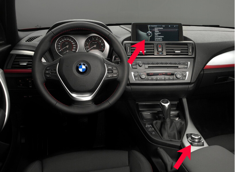
Reset
Reset with multimedia display.
Switch on contact
Select 'SETTINGS VEHICLE'
Select 'RDC'
Select 'Reset' in the menu
Switch off the contact
Reset is required after tyre pressure check, adjustment or replacement of one or more wheels / tyres.
ELECTRONIC PARKING BRAKE ( EPB )


General
Emergency release
Brake pad replacement
Basic settings
Special equipment
FUSES AND RELAYS


FL1 [SB1] Alternator ( 175 A )
FL2 Low power / Heating relay /
Extra air heater ( 40 A )
FL3 Supply voltage of not used ( 110 A )
FL4 Power steering control unit ( 80 A )
FL5 Radiator fan conrol unit thermostat ( 40 A also used ) ( 50 A )
FL6 Glow plug control unit ( 50 A )
FL7 [SB7] High power heating relay /
Battery monitoring control unit /
Additional air heater ( 60 A )
Relay box engine bay:


R1 Relay, additional extra pump refrigerant
R2 Window wiper relay nr.1
R3 Widows wiper relay nr. 2
WARNING LAMPS AND INDICATORS
Specifically per manufacturer with short descriptions and solutions.
Brand specific overview of available warning lamps. For European as well as for American car market.

RECALLS
Contains official information about recalls so that vehicles can always meet the security demands.
Functions
- OEM recalls for security reasons
- Links towards trouble codes and related cases.
Engine stall caused by a fuel supply reduction.
Defect:
Damaged pressure-limiting valve sealing cap in the fuel tank delivery module
Reduced fuel transfer within the fuel tank (left to right)
Engine stall
The fuel gauge indicates that sufficient fuel is present
Number of vehicles affected: 1752
Solution:
Check the fuel pressure of the fuel tank delivery module
Check the clearance of the pressure-limiting valve cap
Renew the fuel tank delivery module if necessary
TECHNICAL DRAWINGS
With tightening torques and links towards parts.


